Introduction to Tank Floor Corrosion and Inspection Challenges
Aboveground storage tanks (AST) have been used to store various liquid products including oil, gas, and chemicals for many years. Over time, corrosion damage may occur on the product side of the tank floor due to the chemical reaction between the product and the carbon steel plates that are welded together to make up the floor.
The soil-side corrosion is due to the reaction between the bottom side of the tank floor and the foundation material. Usually, the top side of the tank floor can be visually inspected once the tank is been properly cleaned and made safe for human entry.
It is much more difficult to inspect the soil side due to the fact that it cannot be seen by the naked eye. Corrosion damage may cause tank floors to leak into the water table and/or contaminate land around the tank.
Various NDT methods have been applied to tank floor inspection. These methods include visual, various forms of eddy current, ultrasonic inspection, and the most widely used currently, and the subject of this article, magnetic flux leakage (MFL).
Evolution of Tank Inspection Methods
The original tank inspections were accomplished with an external inspection only. In some cases this may still hold true today. The original inspections were probably performed by tank owners/operators.
This inspection consisted of the observation of wet spots forming outside of the tank on the ground. The soil may have been replaced or covered over to eliminate the wet spot.
Eventually, the wet spot or spots became significant enough to justify internal inspection. The tanks were cleaned of product residue to various requirements and hopefully made safe for human entry.
Limitations of Early Inspection Techniques
The first internal inspections were visual in nature. If there were holes in the tank floor maybe the product would re-enter through the hole and this spot on the tank floor would be caught with a visual inspection.
The obvious significant problem with this approach is that all the soil-side corrosion flaws that had not yet penetrated 100% could not be found.
In many cases, the tank was returned to service and found to be leaking within a short duration. Some owners/operators may have hit the floors with chipping hammers to try and punch through the floor.
The next approach involved cutting coupons out of the tank floor and examining these coupons for corrosion.
If severe corrosion was found additional coupons were taken. If enough severe corrosion was found the floor might be replaced. If the initial coupons revealed minimum corrosion then the coupon was replaced and the tank was returned to service.
This statistical approach proved inadequate and tanks continued to leak.
The Emergence of NDT and Ultrasonic Testing
Eventually, NDT technicians were contacted to offer a better solution. The simple solution to eliminate the coupon cutting was to take ultrasonic coupons where non-destructive testing would replace destructive coupon cutting.
Areas were marked on the tank floor and ultrasonic readings were taken to determine the remaining wall thickness. These UT coupons eliminated the need to destroy a section of the tank floor. However, this was still a statistical approach. Tanks continued to leak in alarming numbers.
Development of MFL for Tank Floor Inspections
In the 1980s a pipeline company asked at least two pipe inspection companies to produce a magnetic flux leakage device for inspecting tank floors.
This pipeline company knew that these pipe inspection companies had successfully inspected oil country tubular goods such as casing, tubing, drill pipe and line pipe using MFL.
One of the pipe inspection companies agreed to build an MFL unit for tank floors. At approximately the same time, an oil company combined with an NDT equipment manufacturer to produce an MFL tank floor inspection unit. Both of these units used electromagnets.
Today, permanent magnets are more prevalent. Many claims beyond the ability to locate volume losses are currently made. It is incumbent upon inspectors and tank owners to understand the assumptions made by these manufacturers’ claims.
For example, some manufacturers assume the floor is flat, such as the tank floor plates used in the laboratory when developing the bells and whistles on the equipment. One look through the opening of many tanks reveals an undulated floor that is anything but flat.
In this case the assumption of a flat surface would be incorrect and might negatively affect added features such as topside versus soil side discrimination or the determination of remaining wall thickness without UT prove-up.
Principles of Magnetic Flux Leakage
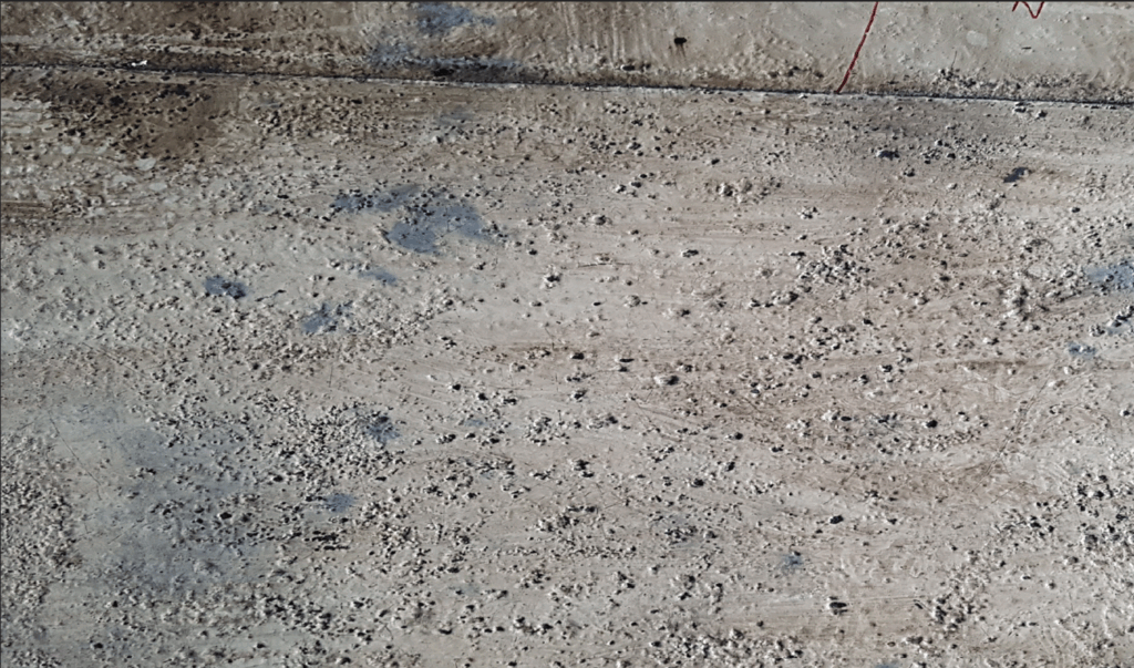
Tank floors that are composed of low-grade carbon steel are suitable for the use of magnetic flux leakage to detect three-dimensional volume losses such as corrosion pitting.
The process incorporates the use of permanent magnets or electro-magnets to introduce lines of flux into the thickness of the tank floor such that the area under test is at or near saturation.
Saturation occurs when the material under test cannot contain any more lines of flux. The material under test (the tank floor plate) is designed such that saturation occurs in nominal areas of the floor where no volume losses exist.
Once a volume loss does occur, then magnetic flux leaks out of the floor plate (therefore magnetic flux leakage). The primary reason for the leakage field is the loss of the volume of metal that holds these lines of flux.
At this point, a flux-sensing detector is required to detect this leakage field.
Types of MFL Sensors: Hall Elements vs. Coils
The most common flux leakage detectors (sensors) for this application are Hall elements and coils. Both sensors offer advantages and disadvantages.
Coils respond to the rate of change of the flux density and Hall elements respond to the absolute value of the flux density.
The flux density present as a leakage field is related to the volume of metal that is missing.
Large-diameter but shallow anomalies may have similar volume losses to small-diameter but deep anomalies. Determining the depth of flaws is usually done with ultrasonic inspection.
MFL is used to rapidly locate the area of interest and UT is the inspection of choice for determining the remaining wall thickness.
The data regarding remaining wall thickness is used in a formula via API 653 to determine corrosion rates so the floor can be inspected again in a timely manner and hopefully prior to leaking.
Challenges in Signal Interpretation
Debates exist concerning the proper sensor to choose. Those that choose Hall elements feel that they are more sensitive than coils. Some may feel the absolute value of the flux density provides a more linear response than the rate of change response from a coil.
It is more linear in response to the volume loss but one cannot assume that linear response to the volume loss is necessarily relevant to linear response to pit depth.
Pits can be narrow and deep or broad and shallow with the same volume loss. These volume losses could give similar signals. Even when using formulas to calculate total volume loss it is impossible to know what formula to use as the shape of the pit on the underside of a tank floor plate is unknown and may vary throughout the tank.
Pits can be round bottom, sharp bottom, and other shapes, none of which are known to the operators of this equipment. In addition, lift off of magnet or sensor may occur causing the signal amplitude to be reduced.
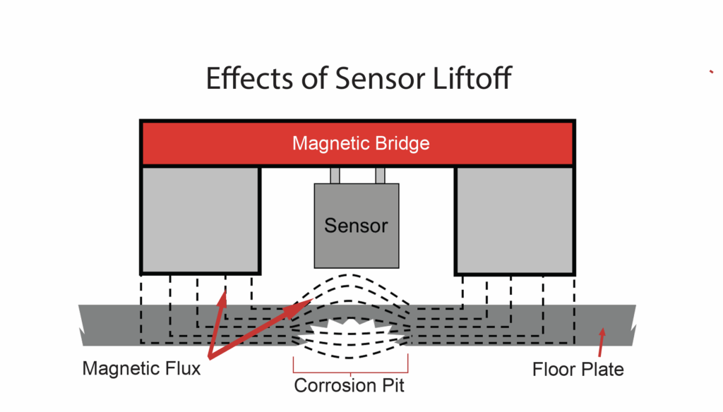
In some cases the scanning head may move closer to the floor causing the signal amplitude to increase. This means that two identical pits could provide completely different signals if lift off occurred in one location and inverse liftoff occurred in the other location.
Electromagnets vs. Permanent Magnets in MFL Equipment
Electromagnets were originally used to saturate the floor plates because permanent magnets did not have the necessary field strength to saturate tank floors when inspection units first became available in the 1980s.
Once permanent magnets were up to the task they replaced electromagnets. The primary reason was power to weight ratio. The electromagnet unit weighed approximately 333 pounds, required a generator, and had an umbilical cord extending from the generator to the inspection unit.
The permanent magnet units usually weighed less than 100 pounds, required no generator and the unit was self-contained with no need for an extended umbilical cable.
Permanent magnet units may be manual, stop-on-defect, or mapping units.
Overview of MFL Inspection Equipment
Manual MFL Units
Manual units are pushed. Typically these are the easiest units to operate, require less training, and are the least expensive. With these manual scanners, the technician is free to scan a plate in any direction.
With the manual unit, the technician does not require a rigid scan pattern as there is no need for an encoder to communicate to the software the location of the sensor. The signals from volume losses are seen in real-time and are located and marked on the floor for ultrasonic prove-up.

The location of the defects is measured from some reference corner of the plate (X,Y) and included in the report. If the number of located indications is too great the operator may suffer from information overload as the real-time display is constantly showing signal responses.
Stop-on-Defect MFL Units
Stop-on-defect units are typically motorized. A threshold is set for signal amplitude such that if the amplitude is reached the drive circuit is interrupted and the unit stops over the defect.
The technician marks the area necessary for prove-up with UT, pushes the reset button, and drives forward until the same situation occurs. The same location report procedure is used.
The unit is heavier, usually motorized and more expensive. The stop-on-defect is helpful if there is difficulty separating signals from noise and signals from volume losses.
However, the operator can once again be overwhelmed if the density of signals is too great as the unit is constantly stopping. Production may become a problem.
Mapping MFL Units
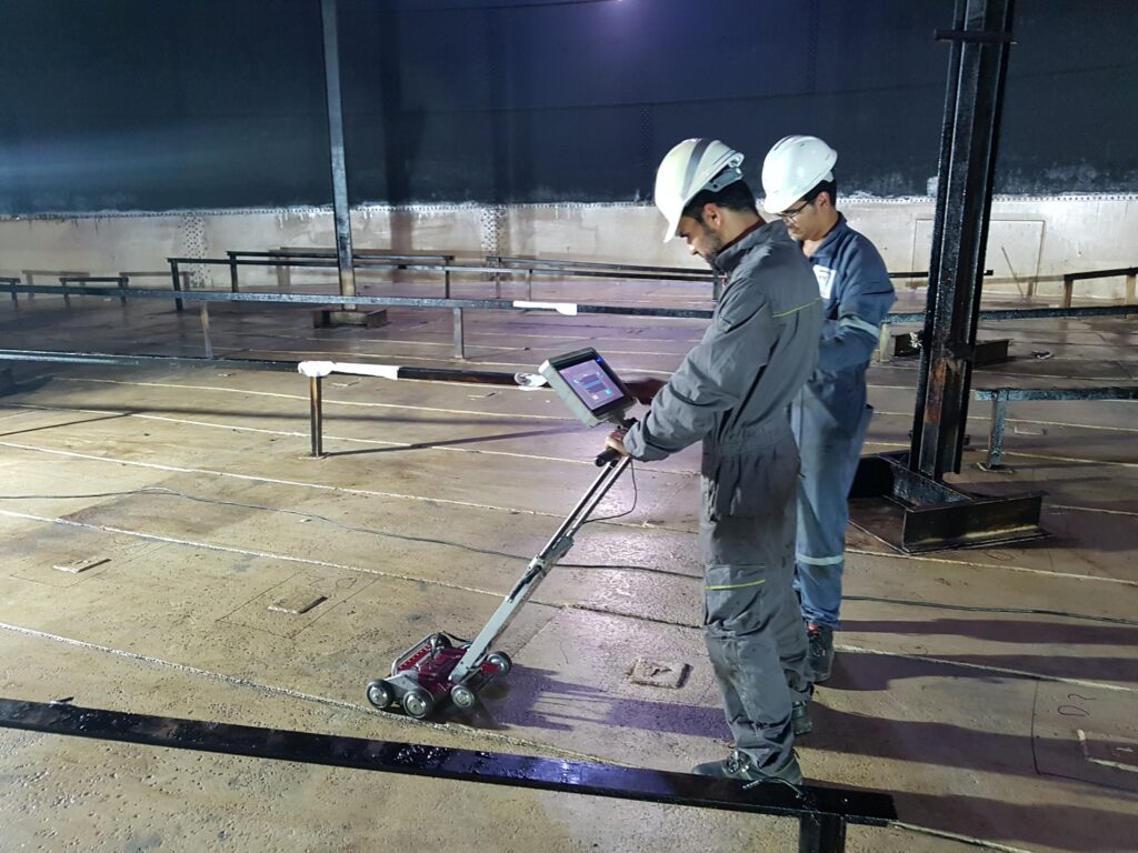
Mapping units require an encoder to tell the software where the sensor is located relative to the tank floor.
These units provide a C-Scan (top-down) color image of the corrosion. Colors change as the volume losses increase.
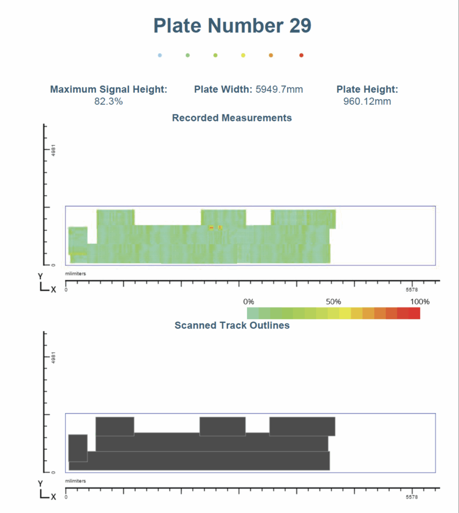
An end user can look at a map of the floor provided by MFL and develop a repair strategy accordingly.
However, the technician requires additional training and the unit may be more sophisticated.
The tank floor must be scanned in rigid scan patterns to simplify the process. Mapping units have scan software and reporting software.
Mistakes can be made when transferring the data from the map onto the floor versus the manual or stop-on-defect unit where the location of the anomaly is marked directly onto the floor using the unit markers.
However, the mapping unit performs best when the defect density is high. The map may simply serve as proof and documentation of the condition of the tank floor.
Standards and Certification Requirements
ASNT has requirements for Levels in MFL and API 653 addresses tank inspection as well as bottom inspections in API 653 Annex G. This is, in my opinion, a valid exercise taken on by personnel in the industry to require technicians and company procedures for tank inspection to be qualified.
All end users should have requirements for inspection companies to meet ASNT and/or API standards to assure end users of tank integrity.
Tank operators can provide in-house inspection and procedure qualifications or can use existing third-party programs for this purpose. T
he object of the exercise is to try to ensure that tank floors are properly inspected using MFL/UT and that re-inspections occur prior to tank floors developing leaks.